Badminton Court Lighting Design Solution

Directory:
1. Badminton Court Lighting Design Considerations
2. Software Simulation
Lighting plays a crucial role in sports facilities, as a well-lit environment enhances athletes' performance. Therefore, the lighting design for these venues must not only comply with required illumination levels but also ensure high lighting quality. To create an effective lighting plan for sports venues, it is essential to first understand the specific sports events and the structural parameters of the venue. Next, one should refer to the relevant lighting standards for sports facilities, select appropriate lamp specifications, arrange the fixtures strategically, and develop the lighting design accordingly.
This paper utilizes DIALux lighting software to create a model of a badminton court, simulating the lighting environment and quantitatively assessing how various light distribution curves, installation locations, and aiming angles of fixtures affect the badminton courts lighting quality. It also explores the feasibility of these factors and aims to achieve an optimal lighting solution for venues hosting "amateur competition" mode badminton events.
1. Badminton Court Lighting Design Considerations
1.1 Selection of Efficient Light Sources
Traditional metal halide lamps are known for their high energy consumption and elevated operating temperatures. Once turned off, these lamps require time to cool down before they can be powered back on. In the event of a power outage during a sporting event, it can be challenging to restore adequate lighting quickly. Utilizing hot-start metal halide lamps or batteries for instant lighting can significantly increase costs. However, with advancements in LED technology, more stadiums are adopting LED lighting. The performance of LED lamps can vary widely among different manufacturers, making direct comparisons difficult. Nonetheless, it is evident that LED lamps are more energy-efficient than metal halide lamps and offer instant start capabilities, effectively addressing the issue of lamp restart after a power failure.
1.2 Arrangement of Lighting Fixtures
The arrangement of lighting fixtures determines their spatial positioning within the venue, which directly impacts illumination levels, uniformity, glare, and shadows on the playing surface. Factors to consider in the arrangement include building height, ease of installation, and routine maintenance. There are typically three methods for arranging lighting fixtures in gymnasiums: top arrangement, side arrangement, and mixed arrangement.
(1) Top Arrangement: Lighting fixtures are evenly distributed above the venue. It is recommended to use axially symmetrical fixtures for optimal light source utilization and uniform horizontal illumination. However, this arrangement may result in poor vertical illumination and a lack of three-dimensionality, which can be detrimental for television broadcasts. This method is best suited for gymnasiums with lower ceiling heights.
(2) Side Arrangement: This method considers both horizontal and vertical illumination, providing a strong three-dimensional effect and good uniformity. It is ideal for sports events where athletes frequently look up, enhancing the quality of television broadcasts. Typically, floodlights or projectors are used on the sides, and careful attention must be paid to the aiming angle of the lamps (the angle between the lamp's peak light intensity direction and the vertical line). This design can be complex, and most stadiums that require TV broadcasting utilize this arrangement.
(3) Mixed Arrangement: This combines both top and side arrangements. While this approach offers various lighting options, it also increases the number of fixtures and overall costs for stadium lighting. It is commonly found in multi-functional stadiums.
1.3 Light Distribution Curves of Lamps
The light distribution curve illustrates how luminous intensity from a light source or fixture is spread in all directions, with the light source at the center of a sphere. The curve is drawn on a plane that intersects the sphere's center and the light axis. The variety of light distribution methods complicates the lighting design for stadiums. Light distribution curves can be categorized into three types based on axial symmetry: axial symmetry, symmetry, and asymmetry. Axial symmetry means that the light distribution curves are generally symmetrical in all directions, as seen in downlights and ceiling lights. Symmetry indicates that the light distribution is symmetrical in the C0° and C180° sections, as well as in the C90° and C270° sections, exemplified by straight tube fluorescent lamps. Asymmetry refers to any section where the light distribution is not symmetrical.
2. Software Simulation
2.1 Project Overview
This project is situated in the gymnasium of a natural gas power generation company. The gymnasium hosts basketball and badminton events, with the two sports areas being separate. The gymnasium measures 40.85 m in width and 20.5 m in depth, featuring a herringbone ceiling made of steel. The ceiling's lowest point is 7 m above the ground, while the highest point reaches 8 m. Considering the building's construction plan and the reflectivity of typical materials, the ceiling has a reflectivity of 0.6. the walls are made of anodized aluminum with a reflectivity of 0.75. and the venue has green PVC sports flooring with a reflectivity of 0.3.
This article focuses on designing the badminton courts lighting scheme. These courts are built to standard dimensions and are primarily used for training, recreational activities, and amateur competitions among company employees, without television broadcasts. Current lighting standards outline the lighting requirements for badminton competition venues with various functions, as detailed in Table 1.
Table 1 Indoor badminton court lighting standards

2.2 Evaluation Metrics
The quality of lighting encompasses factors like average illuminance, uniformity of illuminance, and glare index. During the initial phase of lighting design, the feasibility is primarily assessed through average illuminance and illuminance uniformity. Consequently, this paper analyzes the lighting design proposal based on these two aspects.
Average illuminance is defined as the mean illuminance at each point on a designated surface. As outlined in the "Lighting Design Manual (3rd Edition)", the fundamental formula for calculating average illuminance using the coefficient method is:
Eav = NΦUK/A (1)
In this context, Eav represents the average illuminance on the working surface in lux (lx); N denotes the number of light sources; Φ indicates the luminous flux of the light source in lumens (lm); U is the lamp utilization coefficient; K is the lamp maintenance coefficient, which is set at 0.8; and A is the area of the working surface in square meters (m²).
Illumination uniformity measures the variation in brightness on the reference surface and the contrast between light and dark areas, which indicates the quality of the lighting. A value closer to 1 for illumination uniformity signifies more consistent lighting. This uniformity is quantified using two parameters, U1 and U2. U1 is the ratio of the minimum illumination to the maximum illumination on the badminton court surface, as described in formula (2); U2 is the ratio of the minimum illumination to the average illumination on the badminton court surface, as outlined in formula (3).
U1 = Emin/Emax ( 2 )
U2 = Emin/Eav ( 3 )
In equations (2) and (3), Emax represents the maximum illumination in lux, while Emin denotes the minimum illumination in lux. U1 is beneficial for viewing functionality, and U2 enhances visual comfort.
2.3 Analysis and Comparison of Simulation Results
This study aims to simulate four types of lighting fixtures after examining those available in the market. The key specifications of these lamps are detailed in Table 2.
Following the standard illumination guidelines, the lamps are positioned on either side in two rows and six columns, totaling 12 lamps. The spacing between the lamps is set at 3.13 meters, with a height of 7 meters, and the horizontal distance from the lamps on both sides to the edge of the badminton court is 2 meters. Using the parameters listed in Table 2. a model is created in the DIALux lighting software, as illustrated in Figure 1.
Table 2 Main parameters of lamps

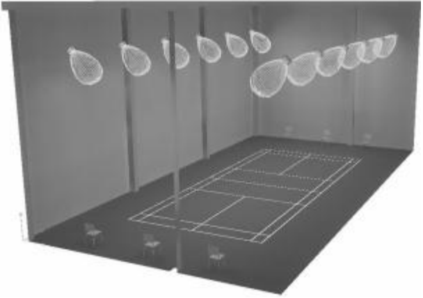
Fig.1 Badminton court model

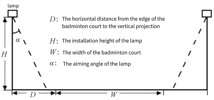
The placement of the lamps complies with the guidelines that prohibit their installation above the main competition area, require them to be positioned 1 meter away on both sides of the sideline, and prevent them from being placed behind the baseline. Given the height restrictions of the gymnasium, the lamps cannot be installed higher than 12 meters. The design of the lighting scheme is not addressed. The boundary line of the badminton court is determined by the doubles sideline. A diagram of the badminton court parameters is illustrated in Fig. 2.
Fig.2 Schematic diagram of the badminton court parameter

Adjust the aiming angles of the four lamps from 10° to 50°, increasing by 10°, and refer to the lighting quality parameter diagram in Fig. 3.
According to current standards, the allowable deviation for the design illuminance at the competition venue should not exceed the standard illuminance value plus 10%. Additionally, the difference between the design illuminance and the standard illuminance must remain within ±10%. Based on these standards, the illuminance range for a badminton court is set between 675 and 825 lx. Figure 3 indicates that the average illuminance from lamp No. 4 is significantly high, with most angles surpassing the standard requirements. The average illuminance from the other lamps falls within the acceptable range for amateur competitions. For amateur events without television coverage, the uniformity of illuminance should meet U1 of at least 0.4 and U2 of at least 0.6. Lamps No. 1. No. 2. and No. 3 exhibit better uniformity, with lamps No. 2 and No. 3 providing relatively high lighting quality. The aiming angle of the lamps can be further adjusted to optimize lighting. Lamp No. 1 has a lower average illumination, and the horizontal distance from the lamp to the edge of the badminton court can be minimized. This adjustment can potentially increase the average illumination while maintaining uniformity.
To assess the viability of lamp No. 1 as a lighting solution, the horizontal distance between the lamps on either side was reduced from 2 m to 1 m, with results displayed in Figure 4.
Figure 4 shows that reducing the horizontal distance improved the average illumination, but it still remains lower than that of lamps No. 2 and No. 3. and the uniformity of illumination slightly decreased, making it unsuitable as a design lamp.
To further evaluate the effectiveness of the lighting solution, the aiming angles of lamps No. 2 and No. 3 were adjusted multiple times in simulations, resulting in a relationship between the aiming angles and lighting quality parameters, as illustrated in Figure 5.
Fig.3 The relationship between the aiming angle of different lamps and lighting quality parameters at a horizontal distance of 2m

Fig.4 The relationship between the aiming angle and lighting quality parameters of No.1 luminaire at different horizontal distances

Fig.5 The relationship between different aiming angles and lighting quality parameters of No.2 and No.3 lamps

Figure 5 illustrates that when Lamp No. 2 is positioned 2 meters away horizontally, the optimal aiming angle is 17°, resulting in the best lighting parameters for the badminton court. In contrast, when Lamp No. 3 is also placed 2 meters away, the ideal aiming angle is 26°, which also yields the best parameters, as detailed in Table 3.
Table 3 indicates that the lighting quality parameters for both setups are quite similar; however, Lamp No. 3 has a lower power consumption, leading to greater energy savings over time. Consequently, the lighting solution chosen is the NVC-NWP618C (bracket type) with a 90° angle, a horizontal distance of 2 meters, and an aiming angle of 26°. The illumination and contour maps for the badminton court are presented in Figure 6.
Fig.6 Illumination map and contour map of badminton court

Table3 Lighting quality parameters of No.2 and No.3 lamps

3. Related Product
