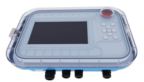
Led Poultry Farm Lighting System: Best Poultry Lighting Controller
Directory:
1. HJF Communication Protocol Development
2. Control System Hardware Design
3. Control System Software Development
4. Best Poultry Lighting Controller
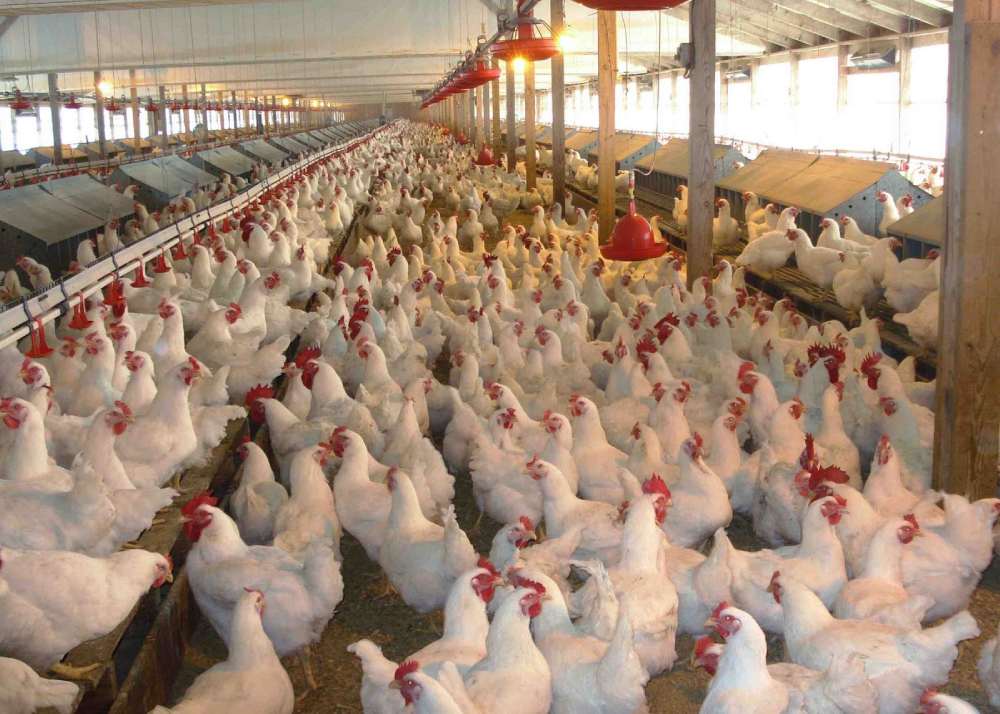
The use of artificial lighting technology has been shown to enhance the growth of broilers, leading to a significant increase in production and a rapid advancement in poultry farm lighting technology for poultry houses in recent years. LED lighting technology, known for its environmental benefits, energy efficiency, high performance, and longevity, is being adopted across various sectors. This paper presents a design for a stable and reliable large-scale LED poultry farm lighting system, based on a renovation project undertaken by a specific company, integrating LED lighting technology.
The design of the LED poultry farm lighting control system for the chicken house encompasses the development of communication protocols, as well as hardware and software design. The communication protocol outlines the physical layer, data link layer, and application layer. The hardware design provides a brief overview of the circuit layout for the master control center, communication channel, and slave control node. Meanwhile, the software design details the programming for the master control's transmission and the slave control's reception.
1. HJF Communication Protocol Development
Given that the system utilizes a serial communication method with a master-slave configuration and operates over a distance exceeding 100 meters, it is essential to establish an effective communication protocol. This protocol was developed independently, drawing inspiration from the OSI (Open Systems Interconnection) seven-layer standard model. The HJF communication protocol encompasses the physical layer, data link layer, and application layer, as illustrated in Figure 1.
fig1 Custom protocols correspond to ISO model hierarchical structure

1.1 Physical Layer
In the physical layer, both the transmitter and receiver of the communication channel utilize an increased driving level to facilitate long-distance communication between the master control center and the slave control nodes. This approach ensures that the slave control nodes do not perceive any differences in the transmission medium or method. Given that the communication volume is relatively small, the protocol can be designed for low-speed communication. To maintain the reliability of the transmitted data, the baud rate for physical layer transmission is set at 300bps. The physical layer employs high and low voltage levels to represent numerical values, with binary data "1" and "0" indicated by "dominant" and "recessive" two-phase or logic states. To enhance resistance to interference, a driving level of 12V is used, as illustrated in Figure 2.
fig2 Control bus level signal
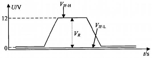
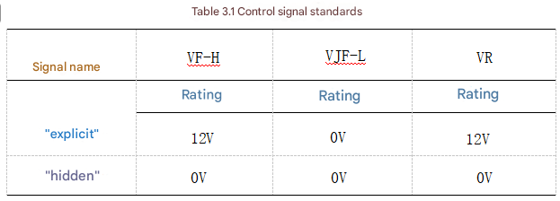
VjFH and VJFL denote the primary and secondary voltage levels of the control bus, respectively. The variation between these two values, VR, defines the standard for the control signal, as illustrated in Table 1.
table1 Control signal standard
1.2 Data Link Layer
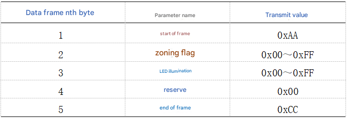
The data link layer specifies the structure of message frames. To guarantee secure, reliable, and standardized communication, the message frame format is organized into five bit fields, as illustrated in Table 2:
table2 Protocol message frame format

The following provides a detailed description of each bit field group:
(1) Frame Start Bit Field Group:
This group contains 1 byte that acts as a signal for the slave control node to recognize a valid data frame. Upon receiving this frame start byte, the slave control node begins to continuously store 5 bytes of data until it receives the frame end bit field group.
(2) Partition Flag Bit Field Group:
This group also consists of 1 byte, which serves as an identifier for the master control center to communicate with 4 different partition slave control nodes. Although 1 byte can theoretically represent 256 identifiers, the HJF protocol enhances communication reliability by splitting this byte into two parts: the upper four bits and the lower four bits. The upper four bits identify the slave control node, allowing for 16 possible nodes, while the lower four bits are used in conjunction with the upper bits through an AND operation. If the result matches the upper bits, it indicates valid data. While this approach limits the number of identifiable slave control nodes, it significantly improves data transmission reliability.
(3) LED Illumination Bit Field Group:
This group consists of 1 byte that allows the slave control node to manage the illumination level of the corresponding partition's LED lamp. The same bit operation technique used in the partition flag bit field group is applied here to ensure reliable data transmission.
(4) Reserved Bit Field Group and Frame End Bit Field Group:
The reserved bit field group is made up of 1 byte, designated for future functional expansions. The frame end bit field group, also 1 byte, indicates the conclusion of a frame message.
1.3 Application Layer
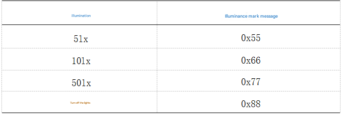
Table 3 illustrates the application layer, which outlines specific message parameters to detail various node partitions and different LED light brightness levels.
table3 Parameter transfer flag
The setup includes one master control center and four partition slave nodes. The communication between the master control center and the slave nodes is defined by the partition flag message, which is detailed in Table 4:
table4 Partition node ID

The partition flag 0x₁1 is used by the master control center to communicate with slave node 1. while 0x22 is for slave node 2. 0x33 is for slave node 3. and 0x44 is for slave node 4. For a feeding cycle, four levels of illumination are needed: 5lx, 10lx, 50lx, and off. The illumination mark message can be found in Table 5.
table5 Illumination mark
2. Control System Hardware Design
The hardware for the system consists of a master control center, a communication channel, and four slave control nodes. The master control center gathers manual operation signals, formats them according to protocol specifications, and transmits them to each slave control node via the communication channel. Each slave control node receives the message from the master control center, interprets it based on the protocol, and manages the lighting of the corresponding partition's LED. The communication channel comprises a transmitter and a receiver, serving as a link between the master and slave controls.
2.1 Master Control Center
(1) Basic Microprocessor System
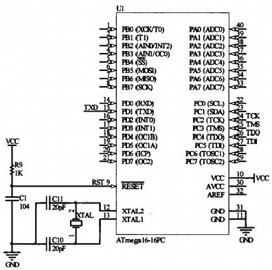
The schematic for the basic microprocessor system is illustrated in Figure 3. It consists of three components: a microprocessor, a crystal oscillator, and a reset mechanism. The chosen microprocessor is an 8-bit, high-performance, low-power ATmega16 microcontroller. To enhance the precision of the communication clock frequency, a quartz crystal oscillator is utilized, known for its compact size, high accuracy, and stability. To ensure reliable communication, the UART serial port baud rate is set to 300bps. Based on calculations, an 8MHz crystal oscillator frequency is selected to satisfy the baud rate requirements. The external circuit for the crystal oscillator is depicted in Figure 3. where capacitors C10 and C11 are chosen to be 20pF to aid the quartz crystal in initiating oscillation. The reset circuit, as shown in Figure 3. employs a classic RC power-on reset. After testing, a resistor R of 1K and a capacitor C of 0.1uF were selected to ensure a stable system reset.
fig3 Microprocessor Minimum System
(2) Design of the main control center power supply
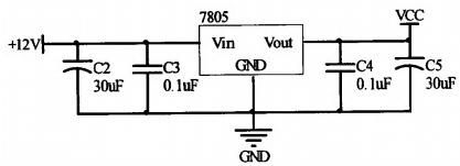
The main control center operates on a 12V DC power supply, while the microprocessor requires a 5V DC voltage. This paper employs a three-terminal voltage regulator circuit, the 7805. to convert and stabilize the 12V DC input into a 5V DC output. The power supply circuit is illustrated in Figure 4. Electrolytic capacitors C2 and C5 are utilized for filtering the input and output voltages, with a typical value of 30uF as specified in the 7805 manual. Additionally, ceramic capacitors C3 and C4 are included to filter out high-frequency harmonics from the input and output voltages, with a typical value of 0.1uF.
fig4 Main control center power circuit
2.2 Communication Channel
Figure 5 illustrates the communication channel, which includes a transmitter and a receiver. The transmitter is located at the main control center, while the receiver is positioned at the slave node. A long-distance control bus connects the two components.
fig5 Communication Channel

The transmitter and receiver are created using a voltage comparator made from an LF353 operational amplifier. TXD represents the serial port output from the main control center's CPU, which sends messages in UART data format. The operational amplifier A1 serves as the transmitter, converting the UART data format into the HJF protocol format with dominant and recessive levels of 12V-0V. RXD is the serial port input for the slave node's CPU, which only understands UART data format. The operational amplifier A2 functions as the receiver, transforming the HJF protocol format back into UART data format.
2.3 Slave Node
(1) Microprocessor Minimum System Design
The design of the slave node's microprocessor minimum system aligns with that of the master control center.
(2) Slave Node Power Supply Design
The power supply for the slave node is sourced from the control partition switch power supply, which provides 36V DC. The microprocessor requires a 5V supply, the partition's LED lighting needs 36V, and the gate of the LED drive MOSFET requires a 15V drive voltage. Consequently, this paper presents the design for the slave node power supply circuit as illustrated in Figure 6.
fig6 Slave node power supply circuit
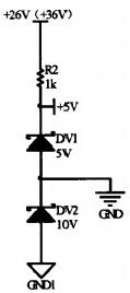
In Figure 6. the voltage regulator tubes DV1. DV2. and resistor R2 create a series voltage divider circuit that reduces the 36V output from the switch power supply into three segments. As depicted, +26V and GND1 are connected to the positive and negative terminals of the switching power supply output, respectively. The ends of the 5V voltage regulator DV1 provide a +5V and ground (GND) power supply for the microprocessor, establishing its power supply circuit. The ground (GND) of both the transmitter and the master control center is shared with the GND of the slave node microprocessor. The +5V and GND1 power supply terminals, which are derived from the series connection of DV1 and the 10V voltage regulator DV2. are utilized to power operational amplifiers A2 (Figure 5) and A3 (Figure 7). The source of MOS tube Q1 (Figure 7) is connected to GND1.
(3) LED Lighting Drive Circuit
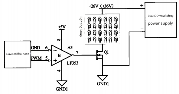
The LED lighting drive circuit is illustrated in Figure 7. In this figure, the slave node microprocessor generates a PWM signal based on the HJF protocol message analysis, which is then transformed into a +15V drive pulse using a voltage comparator made from the LF353 op amp A3. This +15V drive pulse activates MOS tube Q1. thereby controlling the brightness of the LED lighting. The LED lighting is powered by a 36V/400W switching power supply.
fig7 LED lighting driver circuit
3. Control System Software Development
3.1 Design of the Master Control Center Sending Program
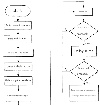
The design of the master control center sending program is illustrated in Figure 8. The program's workflow involves defining necessary variables and initializing the system, which includes setting up the port, serial port, and timer. To prevent the program from malfunctioning, a watchdog program is incorporated; it activates the global middle end, feeds the watchdog, and checks for key presses. If a key is detected, the program waits for 10ms before checking again. If a key press is confirmed, it sends the appropriate message data frame according to the protocol specifications. This delay and subsequent check help to avoid errors caused by key jitter.
fig8 Master control sending program diagram
3.2 Design of the Slave Control Node Receiving Program
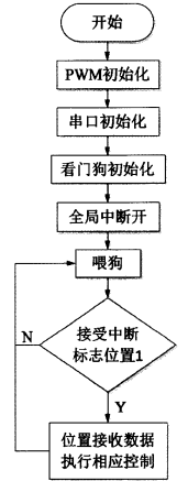
The design of the slave control node receiving program is illustrated in Figure 9. The program operates as follows: it begins by initializing the system, which includes setting up the PWM control register, the serial port register, and the watchdog timer. It then enables global interrupts, resets the watchdog timer, and checks if the serial port receive interrupt flag is activated. If the flag is set, the program parses the incoming data according to the specified protocol and performs the appropriate PWM control to adjust the brightness of the LED lamp. If the flag is not set, the program resets the watchdog timer again and continues monitoring for the receive interrupt flag.
fig9 Slave control node program diagram
4. Best Poultry Lighting Controller
Intelligent Dimmer&Timmer System(IDS Controller)
When using the Master Controller or Slave Dimmer to follow a recommended lighting system, you're providing your animal with smooth dimming and an optimized light spectrum at designated light levels through out the day/production cycle. Not only are you maxmizing your overall return on investment, you'll also experience reduced mortality, improved feed conversion, faster weight gain, reduce stress and other beneficial welfare and productivity enhancements.
