Outdoor Basketball Sport Court Lighting Control System Design
Directory:
1. General System Design
2. System Hardware Design
3. System Software Design
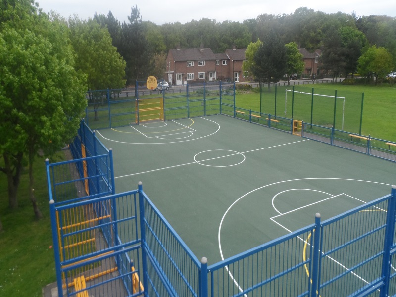
The lighting design for the outdoor basketball court features six sets of LED lights positioned on either side of the court, as illustrated in Figure 1. Specifically, lights 1 and 2 along with backboard 1 are located on the left side, while lights 5 and 6 along with backboard 2 are situated on the right side. Lights 3 and 4 are installed in the center of both sides of the court. The author aims to create an intelligent lighting control system for the outdoor basketball court using ZigBee technology. This system will include light sensor nodes (to determine whether to activate the lights based on external light levels), pressure sensor nodes (to activate the lights when a basketball hits the backboard), and humidity sensor nodes (to assess whether it is sunny based on air humidity, which helps avoid false triggers from large raindrops hitting the backboard). These sensors will be mounted on the back of the backboard to gather data. The collected data will be transmitted to a coordinator via multi-point distributed ZigBee wireless communication. The coordinator will analyze the data according to predefined rules and send control signals to the lighting switch, which will then turn the lights on or off, achieving intelligent control of the court's lighting system.
fig1 Outdoor basketball court lighting plan

1. General System Design
As illustrated in Figure 2. the intelligent lighting control system for the outdoor basketball court comprises terminal nodes, coordinators, lighting switches, host computers, and power supplies. The terminal nodes are integrated into the backboard and are labeled based on the two backboards of the court, specifically as lighting nodes 1 and 2. pressure nodes 1 and 2. and humidity nodes 1 and 2. These terminal nodes connect to the coordinator via a ZigBee wireless transmission network. The coordinator sends control signals to the lighting switch and communicates with the host computer through a serial port. The main steps for implementing the control system are as follows:
(1) The illumination, humidity, and pressure nodes embedded in the backboard measure the current external light intensity, air humidity, and pressure, respectively, and transmit this data to the coordinator;
(2) The coordinator processes the received data based on predefined rules and sends control signals to the lighting switch to adjust the court lighting to no lighting, half-court lighting, or full-court lighting, depending on the results;
(3) The coordinator relays the relevant data to the host computer via the serial port;
(4) The host computer reviews the data or issues commands to the coordinator for remote control purposes.
fig2 Overall design of intelligent lighting control system for outdoor basketball court

2. System Hardware Design
The design of the system hardware primarily consists of a sensor module, a wireless communication module, a lighting switch module, a host computer, and a power module.
2.1 Sensor Module
The sensor module is made up of a light sensor, a pressure sensor, and a humidity sensor.
The BH1750 is a digital light sensor integrated circuit that includes a photodiode, an operational amplifier, an ADC for data acquisition, a crystal oscillator, and more. The photodiode transforms light signals into electrical signals via the photovoltaic effect. The operational amplifier amplifies these signals, and the ADC along with the digital logic circuit converts the resulting voltage into a binary format. The BH1750 features an I2C bus interface for communication with the microcontroller. As illustrated in Figure 3. the BH1750 connects to the GPIO port of the CC2530 using the SCL and SDA ports.
fig3 BH1750 circuit connection diagram

The FSR402 is a resistive force sensor with a sensing area diameter of 12.7 mm and a lifespan exceeding 1 million squeezes. As illustrated in Figure 4. the sensor operates by converting the pressure applied to its film area into a resistance value. The relationship between pressure and resistance is inversely proportional, allowing pressure information to be derived from the resistance value. This sensor boasts high measurement accuracy, lightweight design, compact size, and extended service life.
The DHT11 is a digital sensor for measuring temperature and humidity, featuring a calibrated digital signal output. It consists of a resistive humidity sensing element and a temperature measuring element with a negative temperature coefficient. Its specialized sensing technology and digital module acquisition ensure high reliability and stability. With its small size, low power consumption, and long transmission range (over 20 meters), the DHT11 is an excellent choice for a variety of applications. The circuit connection for the DHT11 is depicted in Figure 5.
fig4 FSR402 circuit connection diagram

fig5 DHT11 Circuit Connection Diagram

2.2 Wireless Communication Module
The design utilizes a ZigBee wireless communication network, known for its low power consumption, affordability, slow data rate, self-configuration capabilities, and flexible network topology. It is commonly employed in smart automation applications such as smart homes, smart cities, and industrial control. The wireless communication module is built using the CC2530 chip, which supports the Z-Stack protocol. The CC2530 is a ZigBee-certified network processor from Texas Instruments that adheres to the IEEE 802.15.4 standard, ZigBee, and ZigBee RF4CE. This chip integrates an 8051 microprocessor, an RF transceiver, 8 KB of RAM, and various robust peripherals and support functions. Additionally, it features three power management modes: interrupt mode, sleep mode, and wake-up mode, which can switch between each other to significantly reduce power consumption.
2.3 Lighting Switch Module
The lighting switch module manages the on/off state of the basketball court lighting based on control signals received from the coordinator. It primarily consists of an optocoupler and a relay, with the optocoupler connected to the relay. The optocoupler facilitates the conversion of electrical signals to optical signals and back, providing strong resistance to interference and enabling unidirectional signal transmission. The relay acts as an automatic switch with isolation capabilities, serving functions such as control, protection, regulation, and information transmission. The coordinator sends a control signal to the relay via the optocoupler to manage the lighting switch state.
3. System Software Design
The software design primarily consists of the terminal node software design and the coordinator software design.
3.1 Terminal Node Software Design
The ZigBee network is established by the coordinator, which sets parameters such as the personal area network ID, the wireless radio frequency communication channel, and the transceiver address. The terminal node requests to join the network and is evaluated to see if its basic parameters match those of the coordinator. If they match, the terminal node successfully connects to the ZigBee network. As illustrated in Figure 6. the flow of the terminal node program is as follows: after the system initializes, the terminal node requests to join the ZigBee wireless network; upon successful connection, a timer is activated, and once the timer expires, the data collected by the sensor is sent to the coordinator.
3.2 Coordinator Software Design
The lighting setup for the outdoor basketball court consists of six LED lights positioned on either side of the court. Lights 1. 2. 3. and 4 are located in the left half of the court, while lights 5 and 6 are in the right half. When the left half is in use, lights 1 and 2 are turned on, and the others remain off; when the right half is in use, lights 5 and 6 are activated, and lights 1 to 4 are off; when the entire court is in use, all lights (1 to 6) are turned on. As shown in Figure 7. the lighting control unit for the full court monitors the half court lighting situation in real-time and performs the necessary actions. If lights 1. 2. 5. and 6 are on simultaneously, lights 3 and 4 will automatically turn on; otherwise, they will remain off. The specific process for controlling the half court lighting is detailed in Figure 8.
fig6 Terminal node program flow

fig7 Basketball court lighting control program flow

The process for controlling the half-court lighting in basketball involves the following steps: once the coordinator sets up the ZigBee network, it waits to receive a terminal node that joins the network. After the terminal node connects, the coordinator collects data from it to assess if the lighting conditions are met. If the conditions are satisfied, the corresponding light for that node is activated for 15 minutes. If not, the coordinator checks if the light has already been on for 15 minutes; if it has, the light is turned off. The terminal node consists of two parts: terminal node 1 and terminal node 2. Node 1. which includes illumination, pressure, and humidity sensors, corresponds to lights 1 and 2. while node 2 corresponds to lights 5 and 6. The lighting condition is defined as having insufficient light near the court while someone is playing basketball, which exerts pressure on the backboard and keeps it relatively dry. Specifically, the sensors detect illumination and humidity levels below a certain threshold, with pressure readings exceeding a specified value.
fig8 Basketball court half-court lighting control program flow

4. Related Blog
Outdoor Basketball Court Light A01

5. Related Blog
led outdoor basketball court lighting
outdoor basketball court lighting layout
outdoor basketball court lighting fixtures
Outdoor Led Basketball Court Flood Lights
outdoor led basketball court lighting design