Outdoor Tennis Court Lighting Layout

Directory:
1. Initial Lighting Layout Scheme
2. Lighting Layout Scheme Comparison
3. Optimization of outdoor tennis court lighting Solutions
4. Important Considerations
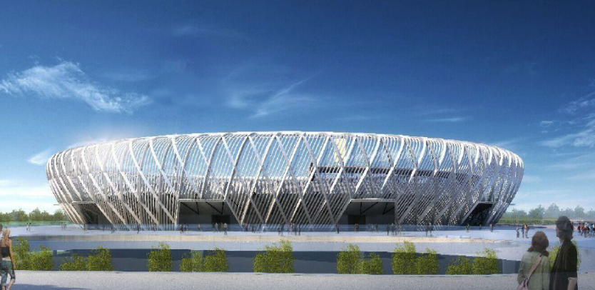
The outdoor tennis court, which accommodates 5000 spectators, is classified as a Class A sports facility and serves as an international standard venue for tennis competitions. It features a specialized acrylic elastic surface layer, a hard tennis court, and a concrete slab for the audience seating. The venue is open-air, covering a total area of approximately 10.961 square meters, with three floors above ground and a height of 17.20 meters. The main structure is a reinforced concrete frame, and the outer decorative grid consists of a large grid steel structure with a two-way oblique diamond space curved surface.
As an outdoor tennis court, it lacks a roof and has a two-way oblique diamond space curved surface large grid steel structure on all four sides. The building does not have any fixtures for lighting, so the lights are arranged in a pole configuration, with poles installed around the court to support the lighting.
Given the numerous parameters involved in designing the stadium lighting and the complexity of the illumination calculations, a three-dimensional spatial model of the lighting installation is created using computer software. This model helps to determine the installation positions and incident angles of the lamps, allowing for simulation calculations to obtain horizontal and vertical illumination values at various points in the stadium. These values are then used to compare different lighting layout schemes to identify the most effective one.
1. Initial Lighting Layout Scheme
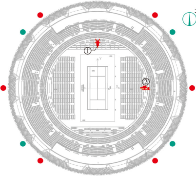
The initial lighting design proposed six poles, with their positions marked in red in Figure 1. Each pole at the corners is equipped with 25 lamps, while the two poles on the east and west sides have 10 lamps each.
fig1

2. Lighting Layout Scheme Comparison
Table 1 presents the illumination and uniformity calculations for HDTV color broadcasts for both the six-pole and four-pole layout schemes (indicated in blue in Figure 1). The data shows that the six-pole layout scheme yields average results, with the lighting effect on the Y-axis being subpar. Although the illumination on the X-axis is better than that of the four-pole layout scheme, the difference is minimal.
table1

In contrast, the four-pole layout scheme demonstrates strong illumination performance on the Y-axis, providing adequate lighting for the main camera, which is beneficial for television broadcasts. Any illumination loss on the X-axis can be compensated by adding more lamps. The uniformity of illumination relies on having a sufficient number of adjustable flood lights. In this design, each pole is equipped with lamps featuring three different light distribution curves, arranged to enhance illumination uniformity.
3. Optimization of outdoor tennis court lighting Solutions
Given that each of the two poles on the east and west sides has only 10 sets of lamps, their contribution to the vertical illumination of the main camera is limited. Therefore, when considering the maintenance of the lamps and poles in the future, the influence of the number of poles on the overall stadium layout, and the need to control project costs, it is advisable to minimize the number of poles. As a result, the initial layout of 6 poles has been reduced by eliminating the poles on the west and east sides, leading to a new configuration of 4 poles. The lamps from the removed poles will be redistributed evenly among the remaining 4 poles, with each now equipped with 20 sets of lamps. Based on this analysis and the resulting calculations, the design has ultimately opted for the 4-pole solution, which will be further optimized in the next design phase.
4. Important Considerations
4.1 When determining the height of the pole, it is essential to consider not only the distance from the site and the projection angle of the lamps but also the relationship between the lowest row of lamps and the building's outer contour to avoid casting shadows from the building onto the site.
4.2 The selection of the lighting layout and the precise positioning of the poles should involve a comparison of multiple options. It is important to balance the changes in horizontal and vertical illuminance, as well as the glare index, that result from adjustments to the lamps' aiming points, in order to reconcile the trade-off between illuminance levels and glare, ultimately striving for optimal lighting performance.