Poultry Lighting Solutions: Chicken Coop Lighting System
Directory:
1 Analysis and Design of Lighting Layout in Poultry Coops
2. Light Distribution Analysis
3. Illumination Control Solution
4. Overall Control Solution
5. Solution of Power Supply Mode
This document presents the comprehensive design of an poultry lighting solution for poultry coops. It details the system's configuration and specifications, employs the distance-to-height ratio to assess lighting distribution and the luminous output of individual lamps, outlines the illumination control strategy, establishes the system control approach, and sets the design criteria for the switching power supply for each section.
1. Analysis and Design of Lighting Layout in Poultry Coops
1.1 Interior Layout of Poultry Coops
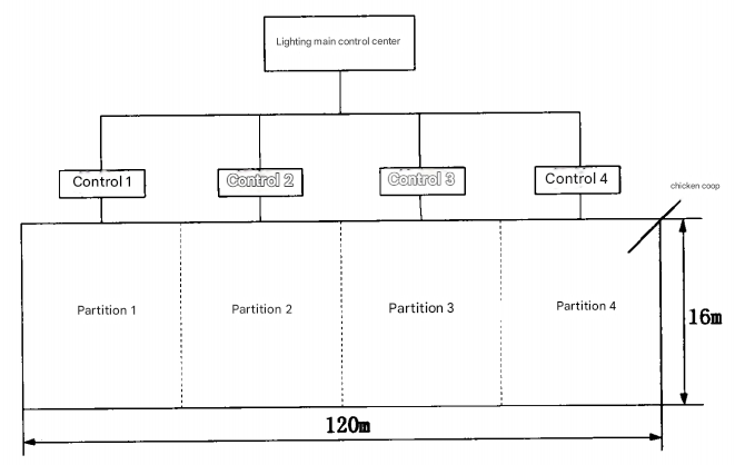
The poultry coop measures 120 meters in length, 16 meters in width, and has a total area of 1.920 square meters. To reduce electricity consumption and costs, the company overseeing the project has requested the implementation of new LED lighting. Considering the varying illumination needs at different stages of the chicken breeding cycle and the growth differences of broilers in various sections of the coop, the company has specified that the poultry coop be divided into four distinct lighting zones. Each zone will have independent lighting control, and the coop will feature a central control hub.
Based on these requirements, the lighting system layout solution illustrated in Figure 1 has been developed, which includes a central control hub and four independently controlled sections. Employees will be able to manage the lighting for each section from the central hub. To ensure uniform lighting conditions for all chickens during the breeding process, light must be evenly distributed across the entire floor of the poultry coop.
Fig 1 Poultry Coop Lighting System Layout
1.2 Lighting Requirements During the Chicken Growth Cycle
Lighting plays a crucial role in enhancing the growth and weight gain of broilers, making lighting technology essential in modern poultry farming. Broilers have different lighting needs at various growth stages. During the brooding phase, newly hatched chicks have limited eyesight, so high-intensity lighting is typically used to support their healthy development by encouraging them to eat and drink. In the adult phase, lower intensity lighting helps to reduce the activity levels of broilers, minimizing pecking and other behaviors, which aids in weight gain. During the market phase, low-intensity lighting helps to calm the broilers, making it easier for employees to handle them.
The lighting requirements for the three stages of the chicken breeding cycle are as follows: from 0 to 7 days old (brooding phase) requires 50 lux; from 8 to 45 days old (growing phase) requires 10 lux; and during the marketing phase, 5 lux is needed. Therefore, lighting must be continuous throughout the chicken breeding cycle, with the required illumination levels changing according to the age of the chickens.
1.3 Control Requirements
fig2 Chicken coop system planning diagram
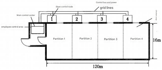
Figure 2 illustrates the lighting control zones in the chicken coop, which include the staff control area and the primary feeding area. The primary feeding area is further segmented into four distinct zones. The main control center is located within the staff control area, while each of the four zones is managed by a subordinate control node. The overall specifications are as follows:
(1) The main control center must be able to individually manage the lighting in each zone, allowing for settings such as off, 51lx, 10lx, and 50lx illumination.
(2) To ensure safety, the power supply voltage must remain below the safety threshold, as employees frequently enter and exit during feeding times.
(3) All lighting equipment must be adequately protected against rain, water, and lightning strikes.
2. Light Distribution Analysis
The lighting in the chicken coop serves as general illumination. It is essential for the floor to have uniform lighting during feeding. The uniformity of illumination within the chicken coop depends on the number, height, and spacing of the installed lighting fixtures. Based on the requirements set by the contracting company, the lighting fixtures in the chicken coop will be installed at a height of 3 meters.
2.1 Distance-to-Height Ratio and Uniformity of Illumination
This paper utilizes the distance-to-height ratio approach to establish the layout and necessary quantity of lighting fixtures. The distance-to-height ratio is defined as the ratio of the maximum distance between two neighboring lamps to their installation height, ensuring consistent illumination on the working surface, as illustrated in Figure 3(a), which represents the ratio of s to h in the system. Assuming no reflections, the ground illumination is determined by the light output from each lamp involved in the setup. Figures 3(a) and (b) depict the schematic representations of the ground illumination calculation method for two and four adjacent lamps, respectively.
fig3 Schematic diagram of distance-to-height ratio
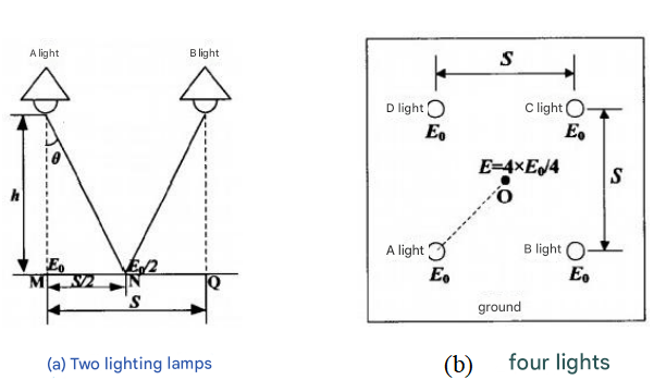
Figure 3(a) illustrates the scenario with two adjacent lamps, A and B, which are identical in type and have the same installation height (h) and distance (s). Points M and Q are located on the ground directly beneath lamps A and B, respectively, while N is the midpoint of the line segment MQ. The angle θ is formed between the vertical line of lamp A and the line connecting lamp A to point N, referred to as the illumination angle. If lamp A provides illumination E₀ to point M, then for point N to receive E₀, both lamps A and B must contribute E₀/2 of illumination at point N, ensuring that the illumination levels at points M, N, and Q are equal or nearly so, thus maintaining uniform ground illumination between the two lamps.
Figure 3(b) depicts the arrangement of four adjacent lamps, A, B, C, and D, positioned in a square formation. To achieve uniform illumination, each lamp must provide E₀/4 of illumination at the geometric center point O, ensuring that the combined illumination at point O equals E₀ from each lamp, thereby guaranteeing uniform ground illumination among the four lamps.
When considering the lighting fixture as a point light source with uniform illumination, the illumination at any point on the ground is influenced by the illumination angle θ. As shown in Figure 3(a), the illumination contribution from lamp A at any ground position can be expressed by the following formula:
Eₙ=E₀cos³θ.
Eh represents the illumination at any point on the ground, while Eo indicates the illumination at point M directly beneath the lamp. The curve illustrating illumination and illumination angles is depicted in Figure 4. By substituting E₀/2 and Eo/4 from Figures 3 (a) and 3 (b) into the formula, we can determine the illumination angles θ₁ and θ₂ necessary for achieving uniform illumination with two adjacent lamps and four adjacent lamps, which are θ=37.5° and θ₂=51°, respectively.
fig4 EA function curve
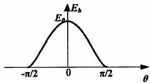
Figure 3(a) illustrates a triangular relationship that reveals the distance-to-height ratio for two and four lamps as follows: S₁/h=2tanC and S₂/h=√2tanθ₂, where S₁ and S₂ are the distances between two adjacent lamps in each scenario. By substituting h=3m, we find S₁≈4.60m and S₂≈5.23m. Given that the width of the chicken coop is 16m, the results indicate that using only two adjacent lamps along the 120m center line of the chicken coop will not provide uniform illumination at the edges. Therefore, to achieve a consistent illumination distribution throughout the chicken coop, four adjacent lamps are necessary.
2.2 Design solution of Lighting for Chicken Coops
The lighting setup for four adjacent lamps requires that the distance between them be less than 5.23 meters. Given the redundant design and the dimensions of the chicken coop, which measures 16 meters in width and 120 meters in length, a total of 96 lamps are arranged in a 4×24 configuration. The lighting design illustration is depicted in Figure 5. Each row contains 24 lamps, spaced 5 meters apart, while each column has 4 lamps, with a distance of 4 meters between them. The spacing between adjacent lamps in both rows and columns is under 5.23 meters, satisfying the necessary criteria. The lighting effect shown in the figure illustrates the coverage area of the 1/4 illumination zone for each lamp. The overlapping 1/4 illumination circles from the four adjacent lamps ensure consistent lighting throughout the area.
Figure 5: Renderings of Chicken Coop Lighting Design

2.3 Required Luminous Flux for Individual Lamps
During the chicken breeding cycle, the initial 7 days constitute the brooding phase, during which the lighting intensity is at its peak. Throughout this period, all lamps in the chicken coop must provide an average illumination of 50 lux on the coop floor.
The relationship between the average illumination on the chicken coop floor and the necessary luminous flux is expressed in formula (2-5)20.21:

In this formula, E represents the average illumination, Φ denotes the required luminous flux, C is the utilization coefficient, K is the maintenance coefficient, and S is the area covered by the lighting lamp.
The utilization coefficient (Cu) is influenced by the lamp's installation height and the wall material. After consulting the utilization coefficient table, Cu is set at 0.9. The maintenance coefficient (K) is determined by factors such as lamp aging and dust accumulation, and is also set at 0.9.
By substituting the relevant values, including the average illumination of 50 lux and the area of the chicken coop, into the formula, we can calculate the total luminous flux Ø:

With a total of 96 lamps, the luminous flux for each individual lamp is:

3. Illumination Control Solution
3.1 Power of Lighting Lamps and Total Energy Consumption
The lighting system utilizes 5730 package SMD LED lamp beads, which have a luminous flux Ø of 601m 122. The number of LEDs in each lighting unit, denoted as n, can be determined as follows:

To ensure redundancy, each lighting unit consists of 24 SMD LEDs, providing a total luminous flux of 1440lm to satisfy illumination needs. The rated power for each 5730 SMD LED is 0.5W, with a working voltage range of 2.9-3.1V. Therefore, the power P₁ required for a single lighting unit is calculated as:
P=0.5W×24=12W
From this analysis, it is established that each lighting unit contains 24 SMD LEDs with a total rated power of 12W. Given the high number of LED beads and power requirements, with each LED rated at 3V and the minimum safe voltage for human contact being 36V, a 2×12 series-parallel hybrid configuration is employed to connect the LED beads in each lighting unit, as illustrated in Figure 10.
fig10 A series connection method for the LEDs within a single lighting unit

In the chicken coop, there are 96 lamps, leading to a total power requirement of:
P₂=12W×96=1152W
3.2 Control of Light Illumination
The A-V characteristic curve for the LED lamp beads is depicted in Figure 11. Similar to standard diodes, they exhibit a forward dead zone, a forward working zone, a reverse cut-off zone, and a reverse breakdown zone.
fig11 The volt-ampere characteristics of light-emitting diodes
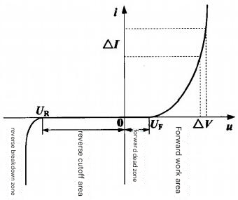
When the forward voltage u applied to the PN junction exceeds the turn-on voltage UF, the LED enters the forward working zone. The characteristic curve in this zone is notably steep, indicating that the LED has very low impedance. Even minor fluctuations in the forward voltage within this zone can lead to significant increases in LED current; for instance, a small voltage fluctuation ΔV can result in a large change in current ΔI. The forward working current of the LED is exponentially related to the applied forward voltage:

Where Is represents the reverse saturation current. The graph in Figure 132531 illustrates the relationship between the luminous flux φ of the LED and the average current Iav. It shows that the luminous flux increases linearly as the average current rises. Thus, by adjusting the current flowing through the light-emitting diode, the LED luminous flux can be regulated, which in turn controls the lighting level in the chicken coop.
fig13 Relationship between LED luminous flux and average current

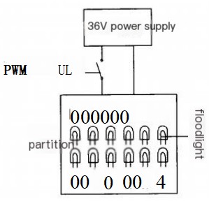
The operating current of the LED lamp bead is closely linked to its working voltage. Additionally, the current significantly impacts the temperature, which directly affects the lifespan of the LED. Therefore, it is essential to design the power supply to maintain a constant voltage. The luminous flux of the LED lamp bead is directly proportional to the average current, allowing for brightness control through average current adjustments. This is achieved using a PWM (Pulse Width Modulation) method to regulate brightness.
Based on this analysis and considering the illumination control needs for each stage and section of the chicken coop feeding cycle, the 24 LED lights in each section utilize the PWM method with an adjustable duty cycle to manage the lighting in their respective areas. The specific schematic is depicted in Figure 14.
fig14 Lighting illumination control
4. Overall Control Solution
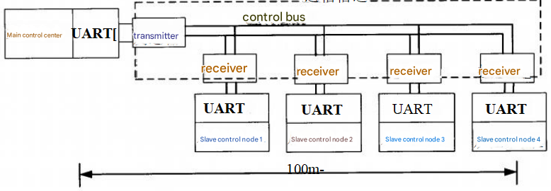
The overall control solution is illustrated in Figure 15. which includes the main control center, communication channel, and four slave control nodes. The control method is implemented using embedded technology. The program controller for both the main control center and the slave control nodes employs the ATmega16 microprocessor, which has an integrated UART, and communicates via serial transmission. Given that the control bus line between the main control center and the slave nodes exceeds 100 meters, the author has established the HJF communication protocol to ensure reliable and stable communication, as shown in the virtual box in Figure 15.
fig15 control system
4.1 Main Control Center
The main control center serves as the interface between the operator and the primary control equipment, as well as managing the slave control nodes. To facilitate ease of use for the breeding staff, the center employs knob switches for controlling lighting and LED indicators to show operational status. Four knobs are utilized to operate four single-pole four-throw switches, which manage the lighting conditions in the chicken coop's four sections: off, 5lx, 10lx, and 50lx illumination. Three LED indicators correspond to the 5lx, 10lx, and 50lx lighting levels. In practice, the main control center compiles the operational requirements for the four zones into HJF communication protocol frames, which are then sent to each partition's control module via a protocol bus.
4.2 Communication Channel
The communication channel is responsible for receiving, parsing, and transmitting master control information to the slave control nodes. The distance from the main control center to the furthest slave control point in the breeding area exceeds 100 meters, while the UART serial port transmission range of the microprocessor is over 10 meters, which can lead to packet loss. To facilitate long-distance communication, a transmitter and receiver are implemented to convert UART data into HJF data format, creating an HJF protocol communication channel through the bus.
4.3 Slave Control Node
The lighting control system utilizes PWM dimming, with the PWM control pulse generated by the slave control node. The control topology is illustrated in Figure 14. The slave control node retrieves the operational requirements by parsing messages from the communication channel receiver and generates a PWM control pulse with the appropriate duty cycle based on these requirements. This PWM pulse regulates the connection between the 36V power supply and the respective lighting fixtures in each partition, thereby controlling illumination by managing the average current.
5. Solution of Power Supply Mode
5.1 Power Supply Parameter Index
The total power needed for the 96 lighting fixtures in the chicken coop is 1152W, with each control partition requiring 288W. To ensure safe electricity usage, a 36V safe DC voltage source is employed. Additionally, to meet safety insulation standards, input and output must be isolated, leading to the use of an isolated topology switching power supply for each control partition. Consequently, a switching power supply is designed for each section based on the analysis and specific enterprise conditions, along with a redundancy margin. The specific parameters for the switching power supply are as follows:
Input voltage: AC 220V mains; Output voltage: DC 36V; Maximum output power: 400W; Maximum output current: 11.12A; Working efficiency: ≥90%; Operating temperature range: -50℃ to +60℃; Insulation characteristics: Input and output are isolated, and all output ports, as well as the AC 220V input ports and ground, can withstand high voltage.
5.2 Common Isolated Topologies
Isolated topologies consist of forward topology, flyback topology, double-ended forward topology, push-pull topology, half-bridge topology, and full-bridge topology. These topologies feature an isolation transformer, enabling them to deliver high voltage and high power output.
5.3 Selection of the Primary Power Supply Topology
After analyzing and comparing various common topologies, and taking into account the 36V/400W power supply standard for each control zone in the chicken coop, this paper identifies the double-ended forward topology as the primary DC conversion topology for the designed switching power supply. The double-ended forward topology offers several benefits:
(1) It is well-suited for small to medium-power switching power supplies, making it an ideal choice for those in the 300-500W range, particularly for the 36V/400W partition power supply discussed in this paper.
(2) The topology features a straightforward structure that is easy to implement, significantly lowering production costs and making it appropriate for mass production, which aligns with business needs.
(3) The switch tube in the double-ended forward topology experiences minimal voltage drop, and the circuit operates without direct bias. This results in lower requirements for power switch tubes and high-frequency transformers.
(4) The topology provides stable output, high conversion efficiency, minimal switching losses, reduced heat generation, and reliable performance, making it suitable for long-term, uninterrupted operation in outdoor environments.